Life is funny. For the longest time, I was navigating a dense fog of thoughts, trying to find my way to a career path that is truly adventurous. I jumped from one thing to another, only to find myself feeling unfulfilled and restless. It’s a journey we’re meant to do when the world presents us with a dizzying array of options.
This blog talks about my journey, my thoughts, it wasn’t about finding a single destination nor it was about the process itself rather but it was about honestly facing my own weaknesses, strengths, and deepest interests. I had to learn to quiet the noise of what I “should” be doing and listen to what I was genuinely drawn to. This meant a lot of introspection and, most importantly, a lot of questioning. Why am I doing this? Does this truly excites me? This continuous self-interrogation, this persistent asking of “the whys, whys, whys,” became my compass. Every moment of confusion became a lesson. By questioning every thought, I began to see the patterns, to understand the motivations, and to finally connect the dots between who I am and what I am meant to do.
The last year of college felt less like a celebration and more like a countdown to disappointment. My degree in Electronics and Communication was one year away, yet I felt like a fraud. Every interview I went on ended with the same polite rejection, a quiet confirmation that I was “very bad” at the very thing my degree was meant to prove I was good at.
Then came the call from Mistral Solutions. A hardware design engineering role. It felt like a lifeline. I cleared every round, got the offer, and was overcome with a feeling of relief and triumph. This was a “core” company; it was a big deal. The pride I felt was so immense that I stopped attending all other interviews. I was set, contained, and finally had something to brag about to everyone.
My first few months at the company were a blur of onboarding and learning. The real challenge began when I was passed over for project assignments. The reason was brutally simple: my knowledge of basic electronics the RLC circuits was lacking. This humbling realization was my wake-up call. I spent months working to fill the gaps, burying myself in the fundamentals, bugging my colleagues, determined to prove my worth.
Finally, I was given a project to design schematics. I poured my life into it, working day and night with little rest. I had an incredible mentor who, though he didn’t have to, sat with me and guided me. He gave me answers; he helped me navigate the problem. My design had a lot of mistakes, some of which we caught, but some of which slipped through.
Then, before the project was even complete, I resigned.
The decision was born from a whirlwind of new insights. I wanted to move to the firmware side of electronics the idea of enabling a piece of hardware and making it do what I wanted was fascinating. I was also starting to see that hardware design, being rule-based, might be automated in the coming decade. I wanted a career with a future and excitement. And yes, I thought software paid more. But most importantly, my mentor encouraged me to pursue a master’s degree, calling it an upgrade for my career.
A year later, I reconnected with few of my old colleagues. I learned that the project I had worked on was a mess. But no one gave me details, only reassurances that I was in a good place now. I chose not to stress over it. The past was out of my control. I made a promise to myself then: I would be accountable for everything I did from that moment on. I would accept when I was bad at something, and I would get second opinions and feedback early on, especially when the stakes were high.
Looking back, the most profound realization came to me while writing this down. I never once asked “why” back then. My habit of questioning everything only started when I turned 28. This leads me to the biggest “why” of all: Why was I able to get a role I wanted, even with my past failures? I mean data showed I am bad it.
The answer was simple: my past didn’t matter because the mistakes and lack of knowledge were just that—in the past. They didn’t define my present because I had chosen to improve. As the saying goes, you are dumb if you don’t ask, but if you do, you are dumb only until you asked. My unwavering focus on my present goal—to become a firmware engineer—was the only thing that mattered. It was a clear, unshakeable ambition that made me eligible, not a flawless resume. I might have gotten lucky, but my first company and mentor played the most crucial role in helping me find the direction I needed.
The years 2021 through 2023 were low-pressure time. I had just joined Intel as an intern, a firmware developer writing algorithms to enable main memory for different technologies. It was a fascinating new world, and my career path seemed to be finally solidifying and exciting.
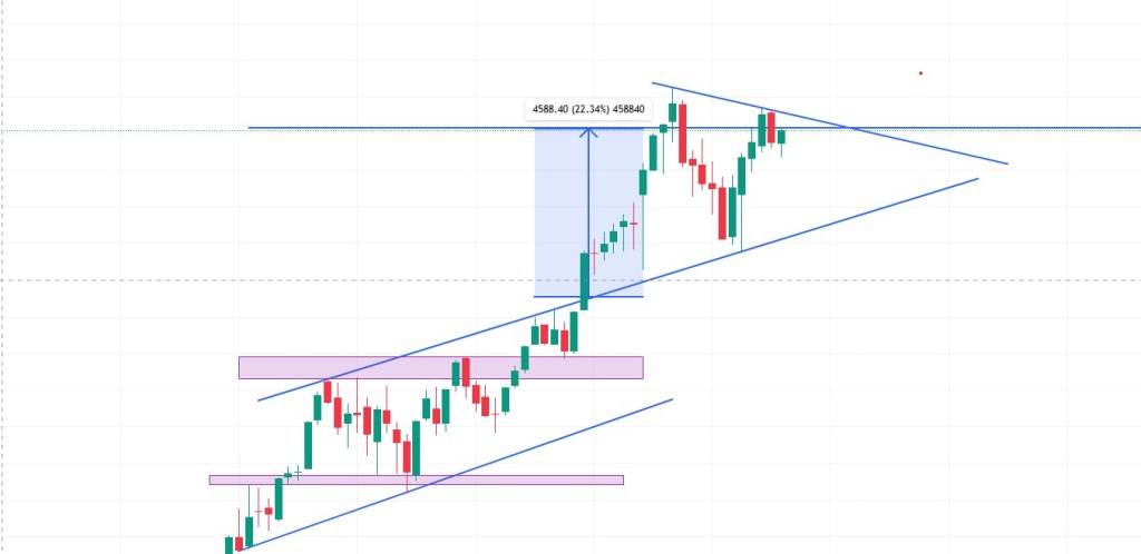
But alongside my new professional life, another obsession was taking hold: stock trading. I dove into it, consuming courses, mastering technical analysis, and watching my charts fill with lines and indicators. I had the dream of becoming a millionaire, a side hustle that would change everything. The journey was a rollercoaster. I made money, I lost money, and by the end of the year, the net result was a big, fat zero. It was a funny paradox, but it was also a heavy one. The mental energy it took was immense. Juggling my day job with the constant wins and losses of trading took a toll, and some months, the losses were so significant that I had very little left to spend.
21-Aug-2025: Nifty50, it worked wonders sometime, sometimes it didn’t. Lets see if the above chart shows how good I am!
During this time, I met someone who was a walking, talking “why.” They questioned everything. My initial approach to life was simple: if I want to do something, I just do it. I was not a curious person in that way; I didn’t feel the need to understand the deeper motivations behind every action. I didn’t realize the importance of their constant questioning until much later.
One day, I decided I couldn’t do it anymore. The trading had to stop. I would quit and instead stick to a few investment patterns I was good at, focusing my energy entirely on my day job. I knew if I told this person about my decision, the first thing they would ask was “why?” This simple thought prompted a deeper self-reflection than I had ever done before. I had to find a real reason, a clear “why” to justify quitting.
The answer, when it finally came, was surprisingly simple. I realized I was good at doing one thing at a time. Multi-tasking was not a strength; it was a distraction, a drain on my energy. I needed to fully immerse myself in a single task to master it, to get it done well and get it done fast. By the end of 2023, my focus had shifted entirely. My day job was no longer just a job; it was my singular pursuit.
I had given up the dream of becoming an overnight millionaire, but in doing so, I had gained something far more valuable: a profound understanding of myself and how I work best. The trading journey and the “why” questions from a curious person had given me the clarity to quit a path that wasn’t working and commit fully to the one that was.
The years 2024 and 2025 were a period of peaceful decisions in my life, though they began in a storm. 2024 was a year of profound physical and mental struggle, a chaos I couldn’t understand. I spent my time getting lost in books, not for pleasure, but for answers. I was searching for the WHY behind my physical and emotional fatigue, finding solace in the quiet solitude that became my comfort.
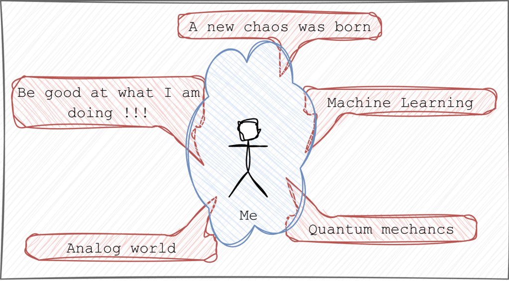
In the midst of this personal turmoil, a new professional chaos emerged: AI/ML. I was consumed by a desire to learn, to understand the fundamental mathematics and the deepest secrets of it. I invested a significant amount of time, but something was missing; I wasn’t excited. The fascination was a quiet, intellectual pursuit, a good investment of time, but not a passionate one. I was a victim of market hype, and the interest, which had been a low hum since 2023, was ultimately superficial.
The beginning of 2025 felt like a breath of fresh air. My health improved, and with it, my mental clarity. This was the start of a new, curious me. My curiosity wasn’t about the world at large or the latest social media trends; it was a deeply personal curiosity—a desire to understand myself and the things I saw and read.
This newfound sense of inquiry brought peace back to my career. There are a hundred things in the world that fascinate me, but I finally understood that true interest is a prerequisite for deep, meaningful learning. I questioned myself, wondering if I was simply a victim of the AI hype, and came to a simple, honest realization: I was not made for it. It sounds easy, but it took a lot of quiet, persistent questioning to arrive there. I liked working on hardware. I loved the process of giving something a life, the introverted world of hardware and firmware that exhibits its power without the world knowing. It was just like me, and that’s how I could be a part of it.
Firmware is a generic term, though, and new “whys” soon followed. This time, it didn’t take years to find the answer. I wanted to be a part of the analog world—the beautifully chaotic world. I want to understand more about analog signal behavior and, one day, maybe even get down to the electron level, where I might control them using the power code.
And here is the funny part of this whole swirly story: I was always part of the analog world from the very beginning…..
If I look at the last five years of my career, I see a journey guided by a sort of quiet magic. By some stroke of luck, I’ve always been on the path I wanted to be on. Maybe sometimes, we’re in the right place already. We just have to ask ourselves, Why am I here? Being in this exact spot might be the perfect thing for us. Something has always been there, making sure I was at the right place. Even when I feel I wasn’t, I am certain that asking “why” will make all the difference in the choices and decisions I make. Life really is a funny thing.
Main memory, or RAM, is the unsung hero behind every program your computer runs. As someone who works on enabling this vital hardware, I’m excited to pull back the curtain and explain its inner workings. This blog will dive into the hardware design of memory, revealing how RAM functions at a fundamental level and how the System-on-Chip (SoC) precisely enables it to execute programs seamlessly.
Contents
DRAM Basics.
DRAM Terminologies.
DRAM Pin-outs (LPDDR4).
DRAM signals.
Memory Controller (MC).
DIMM Types.
DIMM Training.
References
1. DRAM Basics
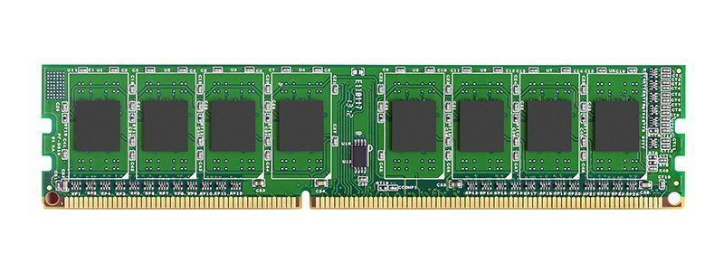
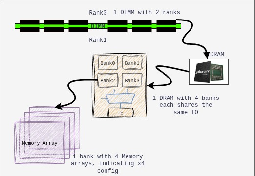
The following is how the DIMM looks like, the eight rectangular chips associated with the circuit are the DRAM chips.
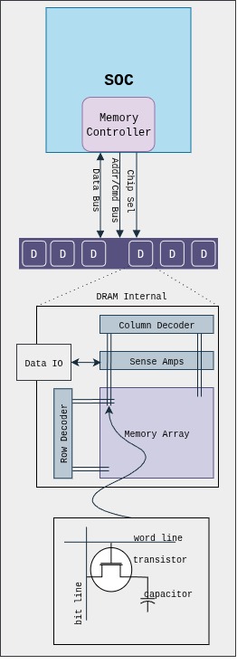
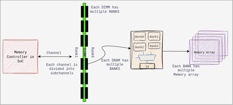
The following illustrates a typical connectivity in a system:
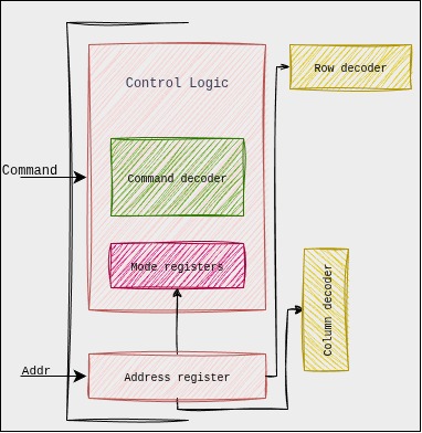
Basic functional blocks of a DRAM: storage cells, storage array, IO structure, sense amplifiers, decoders, control logic and packaging.
The DRAM memory array is a single transistor-capacitor pair for each bit. It is dynamic because capacitors are not perfect devices, and eventually leak; so, each capacitor must be periodically refreshed. Each DRAM die contains one or more memory arrays. Here, the transistor is turned by applying voltage on the gate then a voltage representing the data value is placed onto the bit-line and capacitor is charged. The capacitor retains the stored charge after the transistor is turned off.
The intersection in memory array (above figure) is identified by the intersection of row and column, the memory controller (MC) accesses the stored cell in DRAM chip. The MC acts as an agent between processor and DRAM, the processors requests to the MC and it satisfies it.
The buses connecting from MC to DRAM are JEDEC style, i.e., they are classified by their function and organisation in Data, Address, Command and Chip-select. The Address/Command bus are the same, and composed of row/column strobes, clock, etc… The chip select is responsible to select the rank.
The Sense Amplifiers are used to detect the values stored on the capacitors. The sense amplifier detects the voltage levels in the associated bit-lines. The sense amp first precharges the bit-lines to voltage level that is halfway between logic 0 and 1 and then detected the minute changes.
Sense Amplifiers: The following are the functionality of a sense-amp:
Sense the minute changes in voltage that occurs when transistor is turned on. The sense amp compares the voltage on bit-line vs reference voltage and then resolves to a digital value of 1 or 0.
Restores the value of a cell after the voltage is sensed and amplified.
Acts as a temporary data storage element. The sensed values will remain in the sense amp until another read operation takes place. Thus, sense amp ends up acting as a row buffer to cache elements.
Control Logic: the control logic is responsible for controlling the timings and sequence of signals for the sensing and movement of data, the logic accepts the external signal from MC and generates internal control signals. The modern SDRAMs have complex control logic, and with clock signal, synchronous state machines as control logic is designed. Further, programmable variability is added which allows us to control DRAM devices by using mode registers embedded as part of control logic. The synchronous natures allows pipe-lining, resulting in greater bandwidth.
Mode Registers:
The state machines behavior is controlled using the command signals sent by MC and the programmable mode registers in the control logic. These mode registers are responsible for various control like power consumption, on-die-termination, self-test modes, write recovery, calibration modes etc.
Memory nomenclature (Parallelism can be achieved by playing with below organisation):
DRAM Size Calculation:
/* 4Gb x4 Device */
Number of Row Address bits: A0-A15 = 16 bits
    Total number of rows = 2^16 = 65536
Number of Column Address bits: A0-A9 = 10 bits
    Number of columns per row = 1024
Width of each column = 4 bits
Number of Bank Groups = 4
Number of Banks = 4

Total DRAM Capacity = Num.Rows x Num.Columns x Width.of.Column x Num.BankGroups x Num.Banks

Total DRAM Capacity = 65536 x 1024 x 4 x 4 x 4 = 4Gb

So, for a single DRAM chip with these specifications, the total DRAM capacity is 4 Gigabits (Gb)

/* 4Gb x8 Device */
Number of Row Address bits: A0-A14 = 15 bits
    Total number of rows = 2^15 = 32768
Number of Column Address bits: A0-A9 = 10 bits
    Number of columns per row = 1024
Width of each column = 8 bits
Number of Bank Groups = 4
Number of Banks = 4

Total DRAM Capacity = Num.Rows x Num.Columns x Width.of.Column x Num.BankGroups x Num.Banks

Total DRAM Capacity = 32768 x 1024 x 8 x 4 x 4 = 4Gb

So, for a single DRAM chip with these specifications, the total DRAM capacity is 8 Gigabits (Gb)
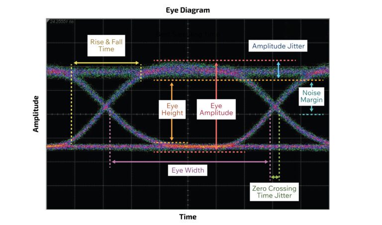
Eye diagram: it is a powerful tool used in high-speed communication to visually assess the quality of a digital signal, where a digital signal is repetitively sampled and overlaid on top of itself, triggered by the data rate or a related clock. The resulting composite waveform often resembles a human eye
Imagine a continuous stream of digital data (a series of 0s and 1s). An oscilloscope captures segments of this data stream, each segment representing a certain number of bit periods. These segments are then superimposed on the same display.
A perfect eye: (Image source: ConnectorSupplier.com)
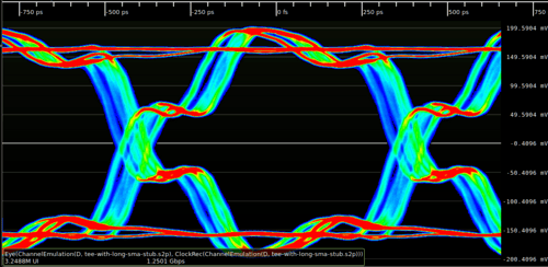
Eye with issue: (Image source: Wikipedia.org)
The effect of this is an increase in signal rise/fall time due to dielectric loss.Impedance mismatches in a transmission line causing reflections shows as defects in the edges of the signal.
Secrets of Eye-diagram:
Eye Opening (Vertical): This is the vertical distance between the top and bottom “rails” of the eye, indicating the voltage margin between logic 0 and logic 1.
Large, clear opening: Good signal-to-noise ratio (SNR), sufficient amplitude to distinguish between 0s and 1s.
Small, closed opening: Indicates noise, attenuation, or inter-symbol-interference (ISI). This can lead to a higher Bit Error Rate (BER).
Eye Opening (Horizontal / Eye Width): This is the horizontal width of the eye at the center, representing the timing margin available for the receiver to sample the data.
Wide opening: Low jitter, good timing margin.
Narrow or “closed” opening: Indicates significant jitter. This reduces the time window in which the receiver can reliably sample the data.
Rise and Fall Times: The steepness of the “slopes” of the eye diagram indicates how quickly the signal transitions between logic states.
Steep slopes (fast rise/fall times): Good high-frequency response, allows for higher data rates.
Shallow slopes (slow rise/fall times): Indicates bandwidth limitations or excessive capacitance, which can lead to ISI and vertical eye closure, especially for short pulse sequences (like 0-1-0 or 1-0-1).
Jitter: The horizontal blurring or “thickness” of the transitions (the “eyelids”). Jitter is the deviation of the signal’s transitions from their ideal timing.
Thick eyelids: High jitter.
Thin, sharp eyelids: Low jitter.
Noise: Vertical blurring or thickness of the “rails” (the stable 0 and 1 levels). This represents random noise superimposed on the signal.
Overshoot/Undershoot: Spikes above the logic 1 level or below the logic 0 level, often caused by impedance mismatches and reflections in the transmission line.
Duty Cycle Distortion (DCD): When the pulse width of a ‘1’ is not equal to the pulse width of a ‘0’. This skews the eye horizontally.
2. DRAM Terminologies
DRAM: Dynamic Random Access memory.
DIMM: Dual In-line Memory Module
x4(by 4), x8(by 8), x16(by 16): the memory chip transmits or receives a number of bits equal to the number of arrays each time the MC accesses the DRAM.
Banks: Memory arrays that operate independently of other set of memory array in a single chip. Each bank is independent of other. Memory interleaving improves performance by splitting physical memory into several banks and distributing consecutive memory addresses across them. The following diagram explains ways in which interleaving is achieved.
JEDEC: Joint Electron Device Engineering Council (JEDEC)
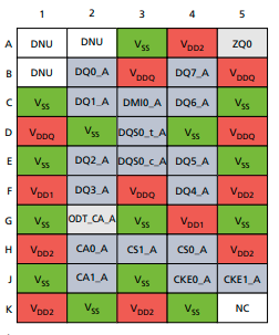
3. DRAM Pinouts and function (LPDDR4)
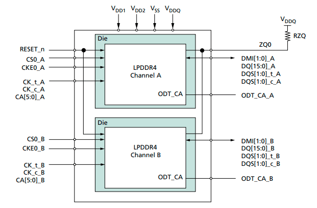
Overview of Dual-Die, Dual-Channel, Single-Rank Package Block Diagram: (Image taken from micron LP4 spec sheet)
Overview of die on chip:
Pin Name
Type
Description
CK_t_A, CK_c_A CK_t_B, CK_c_B
Input
Clock: Differential clock inputs for chA/chB. Address, command and control signals are sampled.
CKE0_A CKE0_B
Input
Clock Enable: Used to activate/deactivate clock. CKE is sampled at the rising edge of CK
CA[5:0]_A, CA[5:0]_B
Input
Command/Address Inputs: Provide the command and address inputs according to the command truth table.
CS0_A CS0_B
Input
Chip Select: Used to select ranks in each channel.
Strobes: Differential clock signals used to strobe data during RW. The strobe is generated by DRAM for READ and by SoC for WRITE. Each byte of data has a data strobe signal pair.
DMI[1:0]_A DMI[1:0]_B
Bidirectional
Data Mask/Data Bus Inversion: It is used to indicate which data is masked and which is inverted in the bus.
ZQ0, ZQ1
Reference
It is used to calibrate the drive strength
VDDQ, VDD1, VDD2
Supply
Power supply for die
RESET_n
Input
Resets all channels if asserted
4. DRAM Signals
Here we will try to understand role of above signals in read/write, which will give us basic understanding of their behavior.
Clock (CK_t, CK_c) (heartbeat of Memory Sub-system):
Purpose: The CLK signal (specifically, a differential pair usually denoted as CK_t and CK_c) is the master timing reference for command and address signals in the DRAM. It dictates when the DRAM samples incoming commands (like READ, WRITE, ACTIVATE, PRECHARGE) and address bits.
The CLK signal is typically generated by the CPU’s memory controller and is distributed to all DRAM chips on the DIMM.
Data Strobe Signal (DQS_t, DQS_c):
Purpose: The DQS signal (also often a differential pair) is the master timing reference specifically for the DQ (data) signals. It’s a “strobe” that tells the receiver (either the memory controller during a read, or the DRAM during a write) exactly when to sample the associated data bits.
Byte-Lane Specific: DQS is unique because it’s byte-lane specific. For every 8 bits (or sometimes 4 bits) of data (DQ[7:0]), there’s typically one associated DQS signal. This is crucial because it helps to maintain tight timing alignment between data and its clock reference, even with variations in trace lengths and signal integrity across a wide data bus.
Bidirectional: Unlike CLK, DQS is a bidirectional signal.
WHY DQS, when we have CLK?
Clock Skew (Flight Time Delay): The physical path (trace length on the PCB) from the memory controller to different DRAM chips on a DIMM, or even to different data pins within the same chip, is never perfectly identical. This causes the global CLK signal to arrive at different times at different points, leading to clock skew.
Data-to-Clock Relationship: The latency between the command (timed by CLK) and the actual data output/input (DQ) can vary slightly due to internal DRAM delays
DQS comes in as a per-byte-lane data clock:
Source Synchronous Timing: DQS implements a source-synchronous timing scheme for data. This means the clock (DQS) travels with the data (DQ) from the source (either the controller or the DRAM). By having DQS accompany the DQ signals on closely matched traces, any propagation delay variations due to temperature, voltage, or trace length affect both DQS and DQ almost equally.
Eliminating Global Skew Issues for Data: Because DQS is generated and transmitted alongside its associated DQ bits, the receiver doesn’t need to rely on a distant, skewed global CLK signal for data capture. Instead, it uses the locally valid and tightly coupled DQS signal, significantly improving timing margins at high data rates.
Summary: CLK is the global reference for CA, ensuring all chips receive instructions simultaneously. And, DQS is the localized, per-byte-lane reference for data (DQ), ensuring precise timing and reliable capture of data at extremely high speeds by traveling with the data signals themselves.
So, Is DQS completely independent of CLK?
The generation and initial synchronization of DQS are still tied back to the main system CLK. DQS is not completely independent of CLK in the broader system. Both the memory controller and the DRAM internally derive and synchronize their DQS generation and reception logic to the main CLK signal. The CLK acts as the overarching timing reference for the entire memory subsystem, dictating command and address timing, and ultimately influencing the precise generation and alignment of DQS. Think of CLK as the master conductor, and DQS as a section leader who then provides precise timing to their own musicians (the DQ bits) based on the master conductor’s beat. (Gemini gives cool responses sometime)
Data Signal (DQ[0:8]):
Purpose: DQ refers to the actual data lines. These are the bidirectional pins on the DRAM chip (and on the DIMM) that carry the information (the 0s and 1s) being written to or read from the memory.
Double Data Rate: As the name suggests, DQ signals transfer data on both the rising and falling edges of the associated DQS signal, effectively doubling the data rate for each DQ pin.
DQ-DQS relationship:
During a READ operation (DRAM to Controller): The DRAM generates DQS and sends it along with the data (DQ) to the memory controller. The DQS is edge-aligned with the DQ data. This means the DQS transitions (both rising and falling edges) occur at approximately the same time as the DQ data transitions. The memory controller uses these DQS edges to capture the incoming DQ data. Why Edge-Aligned from DRAM?: The reason is that the DRAM’s internal data paths have inherent delays. By aligning DQS edges with DQ data transitions as it leaves the DRAM, the DRAM itself can output data as quickly as possible. The burden of creating the optimal sampling window then falls to the more complex and flexible memory controller.
During a WRITE operation (Controller to DRAM): The memory controller generates DQS and sends it along with the data (DQ) to the DRAM. In this case, the DQS is center-aligned (or phase-shifted by 90 degrees) with the DQ data. This means the DQS transitions occur in the middle of the valid DQ data eye. The DRAM uses these DQS edges to capture the incoming DQ data. Why Center-Aligned from Controller?: The memory controller has more precise control over its output timing. By carefully generating DQS to be center-aligned with DQ, it simplifies the data capture logic for the DRAM, which typically has less sophisticated timing adjustment mechanisms than the controller’s PHY.
Command/Address Signal (CA[0:5]):
All commands and addresses are sampled by the DRAM devices based on the edges of this CLK signal. This ensures that all DRAMs on the bus receive and interpret commands (like READ, WRITE, ACTIVATE, PRECHARGE, REFRESH) and addresses (Row Address, Column Address, Bank Address, Bank Group Address) synchronously.
With DDR5 and LPDDR5, the CA bus has evolved to become DDR (Double Data Rate). This means that commands and addresses are sampled on both the rising and falling edges of the CLK
Chip Select (CS):
This control signal that tells a specific DRAM chip (or a rank of chips) whether it should “listen” to the commands and addresses currently on the CA bus by issuing an active-low signal.
Enables CA interpretation: A DRAM will only interpret commands on the CA bus if its corresponding CS# signal is asserted. If CS# is high (inactive), the DRAM ignores the CA bus.
The DQS and CA signals are distinct and independent of each other, but they are related when we consider a certain operation like READ/WRITE/ACTIVATE etc..
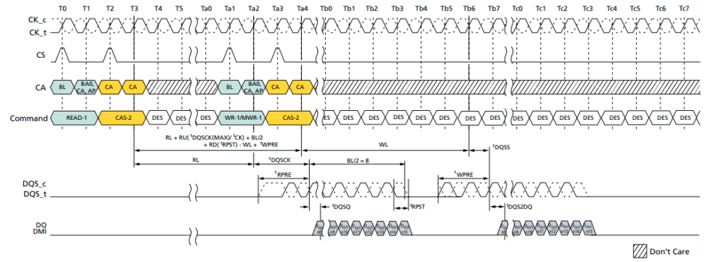
The below waveform shows everything we discussed above for READ and WRITE scenarios, it shows read followed by a write operation. Do not try to understand in detail, the below image was added just to understand how each of the above signal interact and work together execute an instruction. We will get in more detail, in further topics, as we try to understand what JEDEC talks about.
Image source: Micron LP4 datasheet.
5. Memory Controller (MC)
The MC for a given DRAM has nearly as much freedom as he design space for processor specific instruction set architecture, i.e, every other company can have different way of implementing the MC. The DRAM protocols define the interface protocol between MC and DRAM. Note, there is huge disparity in the operating frequency of modern processors and access latency to main memory.
The MC consists of two components:
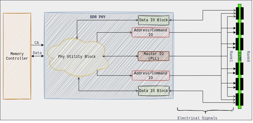
DDR controller: The controller is designed according to JEDEC standard along with the vendors own optimizations and performance capabilities. The controller connects to PHY via DFI interface to complete the solution. The controller includes command scheduler, memory protocol handler, etc…
DDR Phy: The PHY is the direct interface to the DRAM chips. It contains the analog and mixed-signal circuitry responsible for the actual electrical signaling, including drivers, receivers, delay lines, and calibration circuits. The PHY often has dedicated hardware state machines or even a small, embedded processor to execute these training sequences. This allows it to perform the fine-grained, repetitive adjustments required without constantly burdening the main memory controller or CPU.
The PHY takes on much more of the “heavy lifting.” The MC hands over control to the PHY, and the PHY executes complex training sequences, generates necessary commands, and performs analysis, only reporting a “done” status and the final calibrated parameters back to the MC.
The MC and phy, these are strategies (IP owned by Synopsys, Intel, Cadence etc) unique to vendors which are used to obtain high performance and are unique.
6. DIMM Types
UDIMM(Unbuffered DIMM / Unregistered DIMM):
This is the most common type of RAM used in consumer desktop PCs and entry-level workstations. “Unbuffered” means that the MC communicates directly with the DRAM chips on the module.
Pros: Lower latency, lower cost, lower power consumption.
Cons: Due to the direct electrical load on the memory controller, UDIMM’s have limitations on how many modules and how much total capacity a system can support. This limits scalability.
SO-DIMM (Small Outline DIMM):
Description: A much smaller form factor, typically about half the length of a standard DIMM and less pin-counts.
Use Cases: Laptops, notebooks, mini PCs, small form-factor embedded systems
RDIMM(Registered DIMM):
RDIMMs include a register (or buffer) chip on the module for the command and address (CA) and control signals. This register temporarily holds these signals for one clock cycle before sending them to the individual DRAM chips. The data (DQ) lines are still connected directly to the memory controller.
Pros: The register reduces the electrical load on the memory controller for the CA/control lines, allowing for support of more memory modules per channel and thus higher total memory capacities. This also improves signal integrity for these critical signals. They also typically include ECC capabilities
Cons: Slightly higher latency (due to the one-clock-cycle delay introduced by the register), higher cost, slightly higher power consumption than UDIMMs.
LRDIMM(Load-Reduced DIMM):
LRDIMMs take buffering a step further than RDIMMs. They include an Advanced Memory Buffer (AMB) chip that buffers all signals (command, address, control, and data – DQ).
Pros: By presenting only a single electrical load per DIMM to the memory controller (regardless of the number of ranks on the DIMM), LRDIMMs allow for the highest possible memory capacities in a system. They significantly reduce the electrical load on the memory controller, enabling more ranks per channel. They also include ECC.
Cons: Highest latency (due to buffering all signals), highest cost, highest power consumption among the three.
MRDIMM (Multiplexed Rank DIMM):
Also called MCRDIMM for Multi-Channel Registered DIMM.
A new type of DDR5 memory module designed primarily for servers and data centers to significantly increase memory bandwidth and capacity per channel.
MRDIMMs incorporate a high-speed multiplexer or data buffer on the DIMM. This buffer allows the memory controller to simultaneously operate two ranks (or even more in future generations) within a single DIMM module.
CUDIMM is a relatively newer type of DDR5 memory module designed for high-performance client (desktop/consumer) and workstation platforms, primarily to enable much higher frequencies than standard UDIMMs.
The core innovation in CUDIMM is the integration of a Client Clock Driver (CKD) chip directly onto the DIMM module. The CKD acts as a re-driver or buffer for the clock signals (and potentially some control signals). It receives the clock signal from the CPU, regenerates it, and then distributes a clean, strong, and precisely timed clock signal to each of the DRAM chips on the module.
Pros: Higher Frequencies and Overclocking, Improved Stability & Easier Overclocking.
ECC (Error-Correcting Code) DIMM:
Description:ECC DIMMs have an additional chip (found on all DIMMs) per rank that stores parity bits (redundant data). This allows the memory controller to not only detect but also correct single-bit memory errors on the fly, and detect multi-bit errors. They typically have 9 chips per side (e.g., 9, 18, 36 chips total) instead of the usual 8.
Pros: Increased data integrity, system stability, and reliability. Prevents crashes and data corruption due to memory errors.
7. DIMM Training
While designing the implementation, a lot of factors are considered by the designer, like, pins which cause capacitance and inductance, signaling, signal integrity, packaging, synchronization and timings. Failing to consider these, will result in sub-optimal non-functional design.
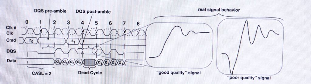
Signal are sent from one device to another in order to communicate. The following timing diagram shows read command to 2 SDRAM devices, where data is moved from DRAM to MC as a response. A good signal is one if it transitions rapidly and settles rapidly from one signal level to another. The poor signal is anything that doesn’t show above behavior.
(Image source: Book: Memory System by Bruce Jacob, David Wang, Spencer Ng)
A basic signaling system is responsible for, where an encoded signal is sent by the transmitter along the transmission line (trace) and is delivered to receiver, the receiver must resolve the value of the signal within valid timing windows from the transmission line.
Need for training’s: Traces on PCBs,
DIMMs are formed from multiple DRAMS mounted on PCBs. the interconnects on PCBs are mostly copper traces and vias that allow electrical signal to deliver from one point to another.
The limitation on the speed and reliability of the data transport mechanism depends on the quality and characteristics of the traces used in the system board.
The above limitation add certain non-idealities like attenuation, reflection, skin effect, cross talk, inter-symbol interference (ISI) and Simultaneous Switching Outputs (SSO).
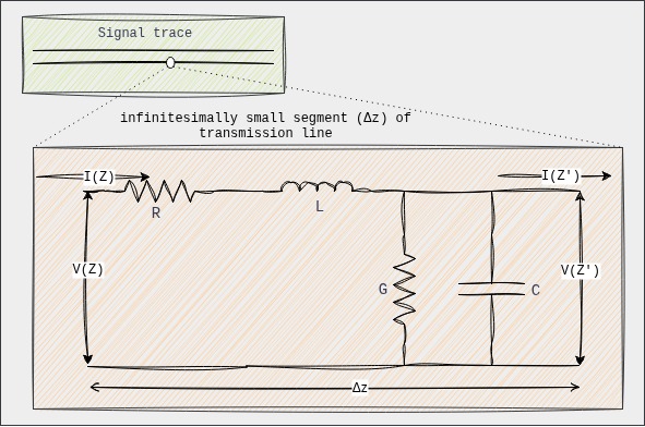
Transmission line characteristics RLC: A transmission line (like a trace on a PCB or a twisted pair) is not a simple wire. At high frequencies or over significant lengths, its properties become distributed, meaning that resistance(R), inductance (L), capacitance (C), and conductance (G) are spread along its entire length, rather than being concentrated at specific points
Let us understand the above model in detail:
Resistance (R):
Series resistive loss in the conductors (wires or traces) of the transmission line.
At higher frequencies, current tends to flow only on the surface of the conductor (the “skin effect”).
Causes attenuation (signal loss) along the line, converting electrical energy into heat.
Inductance (L):
Series inductive property of the transmission line. It accounts for the magnetic field energy stored around the conductors as current flows.
L is relatively constant with frequency up to very high frequencies, as the magnetic field distribution doesn’t change significantly.
Along with capacitance, L primarily determines the characteristic impedance (Z0) and propagation velocity of the signal. Inductance causes a voltage drop.
Capacitance (C):
Shunt capacitive property between the conductors of the transmission line. It accounts for the electric field energy stored in the dielectric material separating the conductors.
Mainly determined by the geometry of the conductors and the permittivity of the dielectric material.
Similar behavior as L.
Conductance (G):
Shunt conductive loss or leakage current through the dielectric material separating the conductors. It’s often referred to as dielectric loss.
G can be frequency-dependent, especially due to dielectric relaxation losses. As frequency increases, the dielectric material absorbs more energy from the oscillating electric field, contributing to loss.
Causes attenuation (signal loss) along the line, dissipating energy in the dielectric.
When RLCG come together as one, then:
Skin Effect: It is a major cause of signal attenuation. The electric current doesn’t flow uniformly throughout the conductor at high frequencies, instead, the flow is limited to a certain depth of the conductor cross section when the signal is switching rapidly.
Dielectric Loss: The dielectric material between the conductors is an insulators and electrons that orbit the atoms in the dielectric material are locked in place in the insulating material. When there is difference in potential between two conductors, the excessive negative charge on one conductor repels electrons on the dielectric toward the positive conductor and disturbs the orbits of the electrons in the dielectric material. A change in energy results in attenuating the voltage signal.
EMI and Cross-talk: The movement of a signal in one direction involves the displacement of electrons in the other direction. A given signal and its current return path from a basic current loop where the magnitude of the current flow in the loop and the area of the loop(the return current path is generally from adjacent path or ground plane) determines the magnitude of the EMI. Noise added into to a given trace by signaling activity from the adjacent traces are collectively referred to as cross-talk. The closely routed signal traces can attack the signal traces and impact timing and signal integrity.
Transmission Line Discontinuities / Improper termination: The trace consist of multiple segments with different characteristic impedance for each segment, signals propagating on the transmission line will be altered at the interface of each discontinuous segment.
Multi-Drop Bus: It is used to carry cmd, addr and data signals from the MC to multiple DRAMS. When a single wire is connected to multiple devices, the propagated signal will partly reflect and gets transmitted across each impedance discontinuity, this will result in more ringing, longer delay and slower rise time. A similar behavior is observed in multiple memory socket configuration.
Skew: A skew is introduced when the trace length between two devices of same signal is different. This happens due to poorly designed board. Skew minimization is an absolute must for high data rate signals. This is generally achieved by by design engineers purposefully adding extra twists and turns to signal paths to minimize skew between signal traces of a parallel bus.
Jitter: It is defined as unwanted variations in amplitude or timing between successive pulses on a given signal line. To ensure the correctness of operation, signaling systems account for variations introduced into system by both skew and jitter. Jitter is difficult to deal with, generally, cuz, of the uncertainty for the cause of it.
Inter-Symbol interference (ISI): Consecutive signals on the same transmission line can have collective, residual effects that can interfere with the transmission of subsequent signals. the interference is referred to as ISI. ISI is a band-pass filter issue. The interconnect is a non-linear low pass filter. The energy of the driver signal resides mostly within the third harmonic frequency. But the interconnect low-pass filter is non-linear, which causes the dispersion of the signal.
Summary: RLCG form the distributed model of a transmission line, defining how signals propagate and how they are affected by the physical properties of the conductor and dielectric. Their frequency-dependent behavior is critical in high-speed digital design, influencing everything from signal attenuation and distortion to characteristic impedance and reflection control.
Timing Synchronization:
Memory Training is a complex process where the CPU and Memory sub-system “train” (calibrate) the timing and electrical characteristics of the DRAM interface. This is crucial due to variations in manufacturing, temperature, and signal integrity across different memory modules and motherboards.
The whole idea of training the memory is to make sure that the signals: Command, Address, Control, Data and clock in a high speed DRAM memory system all propagate on the same type of signal traces in PCBs. To ensure proper synchronization for transmission between MC and DRAM devices. Specifically, Phase-Locked Loop (PLL) or Delay-Locked Loop (DLL) circuits are used to actively compensate for signal skews. Training’s involves things like:
DQ/DQS Training: Aligning data (DQ) and data strobe (DQS) signals.
Read/Write Leveling: Adjusting signal strengths and timings for optimal data transfer.
Vref Training: Calibrating voltage reference levels.
Impedance Calibration: Matching impedance to minimize reflections.
and much more based on MC or JEDEC spec or complexity of the system.
8. References
Memory Systems by Bruce Jacob, David Wang, Spencer Ng
C offers straightforward, simple and complete control over what the developer wants to do, it only requires that developer state their intentions explicitly.
The blog will updated as I learn something new about C. There will be no links directing to another post. Everything will be documented about C here. I will try to keep it as informative and concise as possible. Letss GOO!!!
Topics:
C code structure.
Data types, Operators and Expressions.
Control flow.
Dynamic Memory Management.
Functions and Pointers.
Arrays and Pointers.
Structures and Pointers.
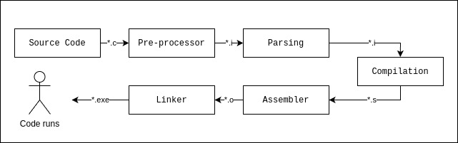
Compilation process and everything.
Working of C on hardware.
Extras (the OG information).
References.
1. C code structure
Refer comments to understand the structure.
// 1. Preprocessor Directives (Include files, macros)
#include <stdio.h> // Includes the standard input/output library for functions like printf, scanf

// Optional: Global variable declarations
// int globalVariable = 10;

// Optional: Function Prototypes (Declarations)
// Tells the compiler about functions defined later in the file or in other files.
void greetUser(char* name);
int add(int a, int b);

// 2. The main() function
// The entry point of every C program. Execution begins here.
int main() {
    // 3. Local variable declarations within main()
    char userName[] = "Alice";
    int num1 = 5;
    int num2 = 3;
    int sum;

    // 4. Statements (Instructions to the computer)
    printf("Hello, world!\n"); // Call to a standard library function

    greetUser(userName); // Call to a user-defined function

    sum = add(num1, num2); // Call to another user-defined function
    printf("The sum of %d and %d is: %d\n", num1, num2, sum);

    // 5. Return Statement
    // Indicates the program's exit status to the operating system.
    // 0 typically means successful execution.
    return 0;
}

// 6. Function Definitions (User-defined functions)
// The actual implementation of the functions declared above.
void greetUser(char* name) {
    printf("Hello, %s!\n", name);
}

int add(int a, int b) {
    return a + b;
}
2. Data types, operators & expressions
Variables and constants: Data objects manipulated in a program. Operators specify what is to be done with them. Expressions combine variables and constants to produce new values. The type of object determines the set of values it can have and what operations it can perform.
Variables:
Names are made of letter and digits; the first character must be a letter. the “_” counts as a letter
We do not start with “_”, but library routines do.
Keywords (if, else if, switch, etc.) are reserved and can’t be used.
Choose variable names that are related to the purpose of the variable.*
We have a number of qualifiers which can be applied to the data types in the following table. That includes: short, long, signed, unisgned. The standard headers <limits.h> and <float.h> contain symbolic constants for all thes sizes.
Data Type
Description
char
1byte, holds one character/letter/number
int
reflecting the natural size of integers on the host machine
float
Single precision floating point
double
double precision floating point
Constants:
An integer constant looks like 0532. A long constant is written with an L, as 123456789L. An unsigned long is constant ends with UL.
A leading 0 on an integer constant means octal, a leading 0x means hexadecimal. These can also have qualifiers like long or unsigned long.
‘x’ is not same “x”: the former is an integer used to produce numeric value of the letter x in machines character set. the latter is an array of characters that contains one character x and a ‘\0’.
The character constant ‘\0’ represents a value of zero(null character). It is done so to emphasize character nature of some expression.
The physical storage of a string needs one more than the number of character written between the quotes due to ‘\0’ at the end.
Enumeration constant: It is a list of constant integer values. The first name in an enum has value 0 and next and so on, unless explicit values are specified like in enum months example below. Enums are an alternatives to #define with the advantage that the values are generated for me. Enumeration offers the chance of checking an so are often better than #define. Further, a debugger may be able to print values of enumeration variables in their symbolic forms.
All variables must be declared before use, although certain declarations can be made implicit by context. A declarations specifies type.
If the variable is not automatic, the initialization is done once only before the program starts executing, and the initializer must be a constant expression.
An explicitly initialized variable is initialized each time the function or block it is in is entered.
External and static variables are initialized to zero by default. Automatic variables for which there is no explicit initializer have undefined values.
int LoopStart, LoopEnd;
char c String[100];

const double pi = 3.14159;
const char msg[] = "error: ";
Escape Sequences:
\a
alert(bell) operator
\b
backspace
\f
formfeed
\n
newline
\r
carriage tab
\t
horizontal tab
\v
vertical tab
\\
backslash
\?
question mark
\’
single quote
\”
single quote
\000
octal number
\xhh
hexadecimal number
Operators: The following table summarizes the rules of precedence(decreases as we go down the row) and associativity of all operators. operators in same line have the same precedence.
Operators
Associativity
() [] -> .
left to right
! ~ ++ — + – * & (type) sizeof
right to left
* / %
left to right
+ –
left to right
<< >>
left to right
< <= > >=
left to right
== !=
left to right
&
left to right
^
left to right
|
left to right
&&
left to right
||
left to right
?:
right to left
= += -= *= /= %= &= ^= |= <<= >>=
right to left
,
left to right
C does not specify the order in which the operands of an operator are evaluated. Example:
x = f() + g();
f() may be evaluated before g() or vice versa. Thus if the f() or g() have variables depend on each other then x can depend on the order of evaluation.
We observe “side-effects” as a by product of the evaluation of an expression, this happens due subtle dependencies on the order in which variables taking part in the expressions are updated. This is one of the place where understanding hardware plays a role.
The % operator cannot be applied to float or double.
The direction of truncation for / and the sign of the result for % are machine dependent for negative operands, as is the action taken on overflow and underflow.
n++ or n– : value is incremented or decremented after assigning the value. ++n or –n: value is assigned after incrementing or decrementing.
Bitwise Operation:
There is no logical or arithmetic shifting for left shift (<<). Zeros are filled in from the rightmost (least significant) end. This is equivalent to multiplication by 2k.
Right shift(>>) for unsigned int(logical shift) behaves similar to left shift. This is equivalent to division by 2k (logical). But for signed int(arithmetic shift), The sign bit (the most significant bit) is replicated (copied) from the leftmost (most significant) end. This ensures that the sign of the number is preserved. With negative integers when a negative number is perfectly divisible by 2k, the arithmetic right shift is same similar to logical shift.
C’s truncation-towards-zero rule for integer division when dividing by powers of two.*
Operator
Operation
& (Testing)
To check the state of the bits of given data.
| (Setting)
Setting required bits of the given data.
&~ (Clearing)
Clearing required bits of the given data.
^ (Toggling)
Toggling required bits of the given data
<< / >> (Shifting)
For direct register manipulation
Type Conversions:
Operator has operands of different types, they are converted to a common type according to a “small number of rules“.
Small number of rules:
Integer Promotion:Any integer type smaller than int (like char, short, enum types, and bit-fields) is automatically converted (promoted) to int or unsigned int before most arithmetic operations.
Usual Arithmetic Conversions (UAC):
Convert the operands to a common type before performing the operation.
C has a rank system for data types: Bool < char < short < int < long < long longfloat < double < long double (floating-point types always rank higher than integer types)
If there are two operands of different types then the “lower” type is promoted to “higher” type before the operation proceeds. Always make sure either operand is of same type.
Assignment Conversions:
When assigning a value of one type to a variable of another type, the value is converted to the type of the variable being assigned to.
Implicit narrowing: This can lead to data loss (e.g., assigning a float to an int truncates the decimal part, assigning a long to an int can overflow). C allows this without a compile-time error, often issuing a warning.
Function Call Conversions (Default Argument Promotions): When passing arguments to a function without a prototype, integer promotions are applied, and float arguments are promoted to double. This ensures consistency and simplifies argument handling for the called function.
Return Value Conversions: value returned by a function is converted to the function’s declared return type
C guarantees that any character in the machine’s standard printing character set will never be negative, so these characters will always be positive in expression. But arbitrary bit patters stored mat appear to be negative on some machines.
Explicit type conversions is done by unary operator called cast.
(type-name) expression;
3. Control Flow
The following are different types of control-flow methods:
if-else & else-if
else can be omitted if not needed. It is used in case an impossible condition comes up or for error detection.
if (expr0)
   -------
else
   .......

(OR)

if (expr0)
   -------
else if (expr1)
   .......
else if (expr2)
   +++++++
else
   =======
Switch
A break statement causes an immediate exit from switch, because cases serve just as labels, after the code for one case is done, execution falls through to the next unless you take explicit action to escape. Even return is used, rarely.
switch (expression) {
  case const-expr: ....
  case const-expr: ----
       break;
  default: ++++
}
Loops–While
while (cond0) {
  ......
  ......
  /* runs the code block until condition fails */
  ......
  ......
}
Loops–For
expr1 and expr3 are assignments or function calls and expr2 is a relational expression.
Operator ‘,‘(comma) is often used in for loops, when a pair of expressions are separated by a comma is evaluated left to right.
for (expr1; expr2; expr3) {
  ......
  ......
  /* runs the code block until expr2 fails */
  ......
  ......
}
Loops–Do-while
do {
  ......
  ......
  /* runs the code block first at least once */
  ......
  ......
} while (cond0);
Break & Continue
while(cond0) {
  //checks if the element of cond0 is present
  if(NotPresent) {
     // check for next element
     continue;
  }
  // if element is present

  ......
  ......
  /* continues with processing the elements */
  ......
  ......

  // if processing fails for element then exit the loop
  if(Error) {
    break;
  }
}
Memory management is crucial for all programs. Sometimes memory is managed during runtime such for automatic variables, while static and global variables are residing in different segment of code(discussed in topic-8). The ability to allocate and deallocate allows the memory to be managed more efficiently and flexibly. “Heap” is that memory which is used to play around.
Steps used for dynamic memory allocation in C are:
Allocate memory.
Use the allocated memory to support the application.
Free the allocated memory.
Function
Description
malloc
allocated memory in heap
realloc
reallocates memory based on previous memory
calloc
allocates and zeros out memory from the heap
free
returns a block of memory to the heap
Dynamic memory is allocated from the heap, with successive allocation calls, there is not guarantee regarding the order of the memory, but, the memory allocated will be aligned according ti the pointers data type.
The heaps size may be fixed when program is created, or it may be allowed to grow. When free() is called, the deallocated memory is available for subsequent use by the application. It is a good habit to free the memory after it is no longer needed.
Dangling Pointers: A pointer referencing to the original memory after it is being freed. It creates various problems, like:
Unpredictable behavior of memory accessed.
Segmentation faults.
Security risks.
5. Functions & Pointers
Function allows modularity, enable developers to build on what others have done instead of starting over from scratch and break a task into small tasks. The small functions are easier to deal with than big one and irrelevant details can be buried in the functions.
A program is just a set of definitions of variables and functions. Communication between the functions is by arguments and values returned by the functions and through external variables. The function can occur in any order in the source file, and the source program can be split into multiple files.
Always declare the function prototype. If there is no function prototype, a function is implicitly declared by its first appearance in a expression. If a name has not been previously declared occurs in an expression and is followed by a left parenthesis, it is declared by context to be a function name, the function is assumed to return an int, and nothing is assumed about its arguments.
#include <stdio.h> // For printf

// 2. Function Prototype (usually placed at the top of the file or in a header file)
double calculateRectangleArea(double length, double width);

int main() {
    double rectLength = 10.5;
    double rectWidth = 5.0;
    double areaResult;

    printf("Welcome to the Area Calculator!\n");

    // 3. Function Call
    // The values of rectLength and rectWidth are passed as arguments
    // The return value from the function is stored in areaResult
    areaResult = calculateRectangleArea(rectLength, rectWidth);

    printf("A rectangle with length %.2f and width %.2f has an area of %.2f\n",
           rectLength, rectWidth, areaResult);

    // Another function call with different values
    printf("Area of a 7.0x3.5 rectangle: %.2f\n", calculateRectangleArea(7.0, 3.5));

    return 0;
}

// 1. Function Definition (can be before or after main, as long as prototyped)
double calculateRectangleArea(double length, double width) {
    double area = length * width;
    return area;
}
A declaration announces the properties of a variable, a definition also causes storage to be set aside and also serve as the declaration for the rest of source files. There must be only one definition of an external variable among all the files that make up the source program.
External variables: they offer greater scope and lifetime. Automatic variables are internal to a function; they come into existence where the function is entered, and disappear when it is left. External variables, on the other hand, are permanent, so they retain values from one function invocation to the next.
Static variables: applied to an external variable or function limits the scope of that object to the rest of the source file being compiled. If the same variable name is used in different files, no conflict will be observed. Static is used for function too, then, it is invisible outside of the file in which it is declared. The static declaration can be internal, such variables are local to a particular function just as automatic variables are, but they remain in existence rather than coming and going each time the function is activated.
static int buf = 0;
Register variables: this advises the compiler that the variable will be used heavily, the variables are to be placed in machine registers, which may result in smaller and faster programs but compilers are free to ignore this advice. The register declaration can only be applied to automatic variables
register int x;
Block Structure: The variables can be defined in a block structured fashion within a function. Variables declared in this way hide any identically named variables in outer blocks, and remain in existence until the matching right brace.
for (n>0) {
   int i; // declare a new i
   while(i<n--) .....
}
Initialization: In the absence of explicit initialization, external and static variables are guaranteed to be initialized to zero, automatic and register variables have undefined initial value. For automatic and register variables, it is done each time the function or block is entered.
File Inclusion:
#include "filename"

or

#include <filename>
The above are replaced by the contents of the file name. If the file name is quoted, searching for the file typically begins where the source program was found; if it is not found there, or if the name is enclosed in “< >”, searching follows an implementation-defined rule to find the file. #include is the preferred way to tie the declarations together for a large program.
Macro Substitution:
#define name replacement_text

Ex:
#define forever for (;;) // infinite loop
Names can be undefined with #undef, usually to ensure that a routine is really a function, not a macro. Formal parameters are not replaced with quoted strings. If parameter name is preceded by a # in replacement text, the combination will be expanded into a quoted string.
The pre-processor ## provides a way to concatenate actual arguments during macro expansion.
#define paste(front, back) front ## back
Conditional Inclusion: It is used to control pre-processing with conditional statements. #if evaluates a constant integer expression, if the expression is non-zero, subsequent lines until #endif, #elif, #else are included. The expression #defined in a #if is 1 if the name has been defined. The #ifdef and #ifndef lines are specialized forms that test whether a name is defined.
#if !defined (ProjA)
#define ProjA

// contents of ProjA are here

#endif
Function Pointers: A function itself is not a variable, but it is possible to define pointers to functions, which can be assigned, placed in arrays, passed to functions, returned by functions, and so on. Functions themselves have addresses in memory, just like variables. A “pointer to a function” is a variable that stores the memory address of a function. This allows you to call a function indirectly through the pointer, pass functions as arguments to other functions, store functions in data structures, and even return functions from other functions.
#include <stdio.h>

int add(int a, int b) {
    return a + b;
}

int main() {
    int (*ptr_to_add)(int, int);
    // The address operator is not necessary. The compiler will ignore even if used.
    ptr_to_add = add;

    int result = ptr_to_add(20, 7); // Implicit dereferencing (more common)
    printf("Result : %d\n", result); // Output: Result : 27

    return 0;
}
Advantage of function pointers:
Callbacks: Implementing event handling.
Generic Programming: Writing more flexible and reusable code
State Machines: Defining transitions in state machines where each state might trigger a different function.
Jump Tables: Creating arrays of function pointers to implement efficient dispatch mechanisms, often used in parsing commands or interpreting byte codes.
Example:

#include <stdio.h>

int addition (int a, int b) {
    return a + b;
}

int multiply (int a, int b) {
    return a * b;
}

int division (int a, int b) {
    if (b == 0) {
        printf("Error: Division by zero!\n");
        return 0; // Or handle error
    }
    return a / b;
}

int main() {
    // Each pointer points to a function that takes two ints and returns an int.
    int (*funcArr[])(int, int) = {addition, multiply, division};

    // Calculate the number of elements in the array
    int num_functions = sizeof(funcArr) / sizeof(funcArr[0]);

    for (int i = 0; i < num_functions; i++) {
        printf("Result of operation %d = %d\n", i + 1, funcArr[i](10, 5));
    }

    return 0;
}
Disadvantage of function pointers: It will slower the running program, as the processor may not able to use branch prediction with pipelining. Pipelining is hardware technology used to improve processor performance. The use of function pointers in table lookups mitigate performance issue.
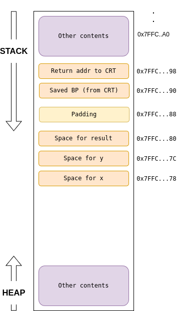
Returning pointer of a local data: Consider the following example. The address of the local_variable returned is not valid once the function returns because the functions stack frame is popped off the stack, while the location may still have contain 100, but will will be overridden if another functions is called.
// DANGER: This function returns a pointer to a local variable.
// The memory pointed to will be invalid after the function returns.
int* create_and_return_local_pointer_DANGEROUS () {
    int local_variable = 100; // This is a local variable, stored on the stack.
    printf("Inside function: local_variable address = %p, value = %d\n",
           (void*)&local_variable, local_variable);

    return &local_variable; // Returning the address of a stack-allocated variable
}

int main () {
    printf("--- Demonstrating the DANGER of returning a pointer to a local variable ---\n\n");

    int *ptr = create_and_return_local_pointer_DANGEROUS (); // ptr now holds a dangling pointer


    return 0;
}
6. Arrays & Pointers
A pointer is a variable that contains the address of a variable. They lead to more compact and efficient code than can be obtained in other ways.
“&” gives the address of an object.
“*” indirection or dereferencing operator, it access the object the pointer points to.
Example:
int x = 1;
int y = 2;
int z[10];

int *ip;     /* ip is a pointer of type int */
ip = &x;     /* ip now points to x */
y = *ip;     /* y holds 1 */
*ip = 0;     /* x is now 0 */
ip = &z[0];  /* ip now points to z[0] */
Example to understand pointer arithmetic:
int Arr[] = {20, 30, 40};
int *ptr = Arr;
int q = 0;
Pointer operation
Arr[0]
Arr[1]
*ptr
q
Description
q = *ptr;
20
30
20
20
Remains same.
q = ++*ptr;
21
30
21
21
Increments the value in addr.
q = ++(*ptr);
21
30
21
21
Increments value in addr.
q = *ptr++;
20
30
30
20
Increments addr. in pointer
q = (*ptr)++;
21
30
21
20
Increments value in addr.
q = *(ptr++);
20
30
30
20
Increments addr. in pointer
q = *(++ptr);
20
30
30
30
Increments addr. in pointer
q = *++ptr;
20
30
30
30
Increments addr. in pointer
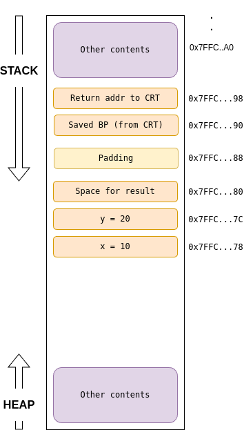
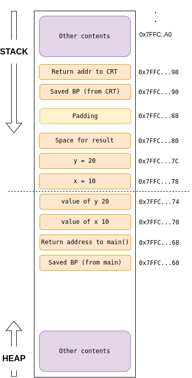
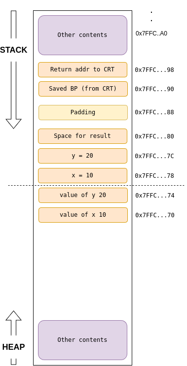
Pass by reference:it is a mechanism for passing arguments to a function where the function receives a reference (or memory address) to the actual argument in the caller’s scope, rather than a copy of its value. This allows the function to directly modify the original variable in the calling code. When you pass the address of a variable (using the & address-of operator) to a function, and the function receives that address as a pointer, it can then use the pointer to de-reference (access the value at that memory location) and modify the original variable.
#include <stdio.h>

// Function that takes pointers to integers
// 'a_ptr' and 'b_ptr' will hold the memory addresses of the original variables
void swap(int *a_ptr, int *b_ptr) {
    int temp = *a_ptr; // Dereference a_ptr to get the value it points to
    *a_ptr = *b_ptr;   // Dereference a_ptr and assign the value pointed to by b_ptr
    *b_ptr = temp;     // Dereference b_ptr and assign the value of temp

    printf("Inside swap function: *a_ptr = %d, *b_ptr = %d\n", *a_ptr, *b_ptr);
}

int main() {
    int x = 10;
    int y = 20;

    printf("Before swap: x = %d, y = %d\n", x, y);

    // Pass the addresses of x and y to the swap function
    swap(&x, &y); // &x gives the address of x, &y gives the address of y

    printf("After swap: x = %d, y = %d\n", x, y); // x and y are now swapped!

    return 0;
}
Output:
Before swap: x = 10, y = 20
Inside swap function: *a_ptr = 20, *b_ptr = 10
After swap: x = 20, y = 10
In C there is relationship between pointers and arrays i.e., any operation that can be achieved by array sub-scripting can also be done with pointers. The pointer version will be fast.
In evaluating a[i] of an array a[10], C converts it to *(a+i) immediately, the two forms are equivalent. Further, consider a pointer *pa=&a[0]; if pa is a pointer, expressions may use it with subscript; pa[i] is identical to *(pa+i). A pointer is a variable, so pa=a and pa++ are legal. But an array name is not a variable; constructions like a=pa and a++ are illegal.
Pointers and integers are not interchangeable. Zero is an exception: the constant zero may be assigned to a pointer, and a pointer ma be compared with constant zero. The symbolic constant NULL as a mnemonic for 0 that this is a special value for a pointer.
Pointers to pointers: A pointer that points to another pointer. This is the most direct interpretation of “multi-dimensional pointer” when you go beyond two dimensions.
Syntax: type **pointer_to_pointer_name;

This means pointer_to_pointer_name holds the address of another pointer, which in turn holds the address of a type variable.
#include <stdio.h>

int main() {
    int x = 100;
    int *ptr_to_x = &x;       // ptr_to_x points to x
    int **ptr_to_ptr_to_x = &ptr_to_x; // ptr_to_ptr_to_x points to ptr_to_x

    printf("Value of x: %d\n", x); // Output: 100
    printf("Value pointed to by ptr_to_x: %d\n", *ptr_to_x); // Output: 100
    printf("Value pointed to by ptr_to_ptr_to_x: %d\n", **ptr_to_ptr_to_x); // Output: 100

    // You can modify x through the double pointer
    **ptr_to_ptr_to_x = 200;
    printf("New value of x: %d\n", x); // Output: 200

    return 0;
}
Passing a Pointer to a Pointer: It’s an extension of “call by reference”. When a pointer is passed to a function, it is passed by value. If we want to modify the original pointer and not the copy of the pointer, we need to pass it as a pointer to a pointer.
The following example explains why passing a single pointer will fail:
#include <stdio.h>
#include <stdlib.h>

void allocate_and_fail(int *ptr) {
    // This pointer 'ptr' is a local copy of my_ptr's address from main.
    // The memory is allocated, and 'ptr' points to it.
    ptr = (int*)malloc(sizeof(int));
    if (ptr == NULL) return;
    *ptr = 100;

    // When this function ends, the local copy 'ptr' is destroyed.
    // 'my_ptr' in main is still NULL. The allocated memory is now leaked.
}

int main() {
    int *my_ptr = NULL; // Initially, it points to nothing.

    allocate_and_fail(my_ptr); // Passing by value (a copy of the NULL address).

    if (my_ptr == NULL) {
        printf("my_ptr is still NULL. Allocation failed.\n");
    }

    return 0;
}
In this case, allocate_and_fail receives a copy of the NULL value. It successfully allocates memory, but it only changes its local copy of the pointer. The original my_ptr in main remains unchanged.
Now, when we re-write the above code using pointer to pointer:
To change my_ptr itself, you must pass its address. Since my_ptr is already a pointer (int*), its address is a pointer to an int*, which is an int**.
here#include <stdlib.h>

// The function now takes a pointer to a pointer to an integer (int**).
void allocate_and_succeed(int **ptr_to_ptr) {
    // We are at level 2 of indirection.
    // *ptr_to_ptr dereferences to the pointer variable from main.
    // We can now assign a new address to it.
    *ptr_to_ptr = (int*)malloc(sizeof(int));

    if (*ptr_to_ptr == NULL) return;

    // Now, let's dereference one more time to access the memory itself.
    // **ptr_to_ptr is equivalent to *my_ptr in main.
    **ptr_to_ptr = 100;
}

int main() {
    int *my_ptr = NULL;

    // Pass the address of my_ptr (which is of type int*)
    allocate_and_succeed(&my_ptr);

    if (my_ptr != NULL) {
        printf("my_ptr is no longer NULL! It points to %d\n", *my_ptr);
        // Clean up the dynamically allocated memory
        free(my_ptr);
        my_ptr = NULL;
    } else {
        printf("Memory allocation failed.\n");
    }

    return 0;
}
Array of Pointers: An array where each element is itself a pointer. This can then be used to create “jagged” arrays or manage dynamically allocated memory. An array of pointers is simply an array where each element holds an address (a pointer) to something else. This “something else” could be a single variable, or the beginning of another array.
Syntax: type *array_name[size];

type *: Each element in the array is a pointer to type.
array_name[size]: array_name is an array of size elements.
For strings:
#include <stdio.h>

int main() {
    // This creates an array where each element is a pointer to the first character of a string literal.
    const char *names[] = {
        "Alice",
        "Bob",
        "Charlie",
        "David"
    };

    printf("First name: %s\n", names[0]);    // Output: Alice
    printf("Third name: %s\n", names[2]);    // Output: Charlie

    // You can iterate through it
    for (int i = 0; i < 4; i++) {
        printf("Name %d: %s\n", i + 1, names[i]);
    }

    return 0;
}
For jagged array:
#include <stdio.h>
#include <stdlib.h> // For malloc and free

int main() {
    int rows = 3;
    // An array of pointers to integers. Each pointer will point to a dynamically allocated row.
    int **jagged_array;

    // Allocate memory for 'rows' number of integer pointers
    jagged_array = (int **) malloc(rows * sizeof(int *));
    if (jagged_array == NULL) {
        perror("malloc for rows failed");
        return 1;
    }

    // Allocate memory for each row with different lengths
    int row_lengths[] = {3, 5, 2};

    for (int i = 0; i < rows; i++) {
        jagged_array[i] = (int *) malloc(row_lengths[i] * sizeof(int));
        if (jagged_array[i] == NULL) {
            perror("malloc for row failed");
            // Free previously allocated rows before exiting
            for (int j = 0; j < i; j++) {
                free(jagged_array[j]);
            }
            free(jagged_array);
            return 1;
        }
        // Initialize values
        for (int j = 0; j < row_lengths[i]; j++) {
            jagged_array[i][j] = (i + 1) * 10 + j;
        }
    }

    // Print the jagged array
    printf("Jagged Array:\n");
    for (int i = 0; i < rows; i++) {
        for (int j = 0; j < row_lengths[i]; j++) {
            printf("%d ", jagged_array[i][j]);
        }
        printf("\n");
    }

    // Free the allocated memory (important to prevent memory leaks)
    for (int i = 0; i < rows; i++) {
        free(jagged_array[i]); // Free each row
    }
    free(jagged_array); // Free the array of pointers itself

    return 0;
}
Pointer toMulti-dimensional arrays: A single pointer that points to an entire multi-dimensional array. When you have a true multi-dimensional array in C, like int arr[3][4];, this array is stored contiguously in memory in row-major order. A pointer can be made to point to this entire structure or its rows.
//main ()
int main  (int argc, char *argv[]) { ... }
For 1D array:
#include <stdio.h>

int main() {
    int arr[5] = {10, 20, 30, 40, 50};
    int (*ptr_to_array)[5]; // Declares ptr_to_array as a pointer to an array of 5 integers

    ptr_to_array = &arr; // ptr_to_array now points to the entire arr array

    printf("Value at (*ptr_to_array)[0]: %d\n", (*ptr_to_array)[0]); // Accessing the first element
    printf("Value at (*ptr_to_array)[2]: %d\n", (*ptr_to_array)[2]); // Accessing the third element

    // You can also use pointer arithmetic on ptr_to_array
    // Note: ptr_to_array + 1 would point to the memory location *after* the entire arr array
    // To move within the array using the pointer, you typically dereference it first
    printf("Value at *(*ptr_to_array + 1): %d\n", *(*ptr_to_array + 1)); // Accesses the second element (20)
    printf("Value at (*ptr_to_array)[1]: %d\n", (*ptr_to_array)[1]); // Equivalent and clearer
    return 0;
}
For 2D array: A pointer to a multi-dimensional array maintains information about the dimensions of the array it points to (except for the first dimension, which is implicitly handled). This is crucial for correct pointer arithmetic when moving between rows/sub-arrays.
#include <stdio.h>

int main() {
    int matrix[3][4] = {
        {1, 2, 3, 4},
        {5, 6, 7, 8},
        {9, 10, 11, 12}
    };

    // ptr_to_row is a pointer that points to an array of 4 integers.
    // It can point to any row in the 'matrix'.
    int (*ptr_to_row)[4];

    ptr_to_row = matrix; // 'matrix' itself decays to a pointer to its first row (&matrix[0])

    printf("Accessing matrix[0][0] via ptr_to_row: %d\n", ptr_to_row[0][0]); // Output: 1
    printf("Accessing matrix[0][1] via ptr_to_row: %d\n", ptr_to_row[0][1]); // Output: 2

    // Move to the next row (matrix[1])
    ptr_to_row++;
    printf("Accessing matrix[1][0] via ptr_to_row: %d\n", ptr_to_row[0][0]); // Output: 5
    printf("Accessing matrix[1][2] via ptr_to_row: %d\n", ptr_to_row[0][2]); // Output: 7

    // You can also assign the address of a specific row
    ptr_to_row = &matrix[2]; // ptr_to_row now points to the third row
    printf("Accessing matrix[2][3] via ptr_to_row: %d\n", ptr_to_row[0][3]); // Output: 12

    return 0;
}
Command-line arguments:
Syntax: type (*pointer_name)[size];

type           : The data type of the elements in the array.
(*pointer_name): The parentheses are crucial here. They indicate that pointer_name is a pointer. Without them,
                 pointer_name would be an array of pointers, which is different.
[size]         : This specifies that the pointer points to an array of size elements.
When main is called, it is called with two arguements:
argc : argument count, is the number of command-line arguments the program was invoked with.
argv : argument vector, is a pointer to an array of character strings that contain the arguments, one per string.
By convention, argv[0] is the name by whcih the program was invoked, so argc is at least 1. If argc is 1, there is no command-line arguments after the program name.
Since, argc is a pointer to an array of pointers, we can manipulate the pointer rather than index the array.
7. Structures & Pointers
A structure is a collection of one or more variables, possibly of different types, grouped together under a single name for convenient handling. They permit a group of related variables to be treated as a unit instead of as separate entities.
//Structure definition
struct point {
  int x; // member or tag
  int y;
}
A structure declaration that is not allowed by a list of variables reserves no storage; it merely describes a template or the shape of a structure. If the declaration is tagged, however, the tag can be used later in definitions of instances of the structure.
Structure can be nested. One representation of a rectangle is a pair of points that denote the diagonally opposite corners:
//Nested structure definition
struct rect {
  struct point pt1; // member or tag
  struct point pt2;
}

int main () {
   struct rect screen;
   screen.pt1.x = 10;
   ...
   ...
   ...
}
Structure and Functions:
Few things to note in makepoint function that it returns a a struct point instead of any integer.
// makepoint: make a point from x and y components
struct point makepoint (int x, int y) {
   struct point temp;

   temp.x = x;
   temp.y = y;

   return temp;
}

struct rect screen;
struct point middle;
struct point makepoint(int, int);

screen.pt1 = makepoint (0, 0);
screen.pt2 = makepoint (XMAX, XMAX);
middle = makepoint ((screen.pt1.x + screen.pt2.x)/2, (screen.pt1.y + screen.pt2.y)/2);
There is no-conflict between the argument name and the member with the same name; indeed the re-use of the name stresses their relationship.
If a large structure is to be passed to a function, it is generally more efficient to pass a pointer than to copy the whole structure. The declaration format in in below code snippet.
struct point *pp;
struct point origin;

pp = &origin;
The notation to access the member of the structure
pp->member-of-structure;
Self-referential structure: It structure in C is a structure that contains at least one member which is a pointer to a structure of the same type. In simpler terms, it’s a blueprint for a data element that also includes instructions on how to find the next data element of the same kind.
Syntax:
struct tag_name {
    // Data members of the structure
    data_type member1;
    data_type member2;
    // ...

    // Pointer to the same type of structure
    struct tag_name *next_node;
};
Key Point: It’s a pointer, not the structure itself!
Typedef: it is used for creating new data type name. Syntactically typedef is like the storage class extern, static, etc. It doesn’t create a new type in any sense, it merely adds a new name for some existing type.
Advantage of using typedef:
Parameterize a program against portability problems.
Provide better documentation for a program.
Exmaple:
typedef int length;

// makes the name length a synonym for int.
length len, width;
Unions: it is a variable that holds objects of different types and sizes, with the compiler keeping track of size and alignment requirements. Unions provide a way to manipulate different kinds of data in a single area of storage, without embedding any machine-dependent information in the program.
Exmaple:
union u_tag {
   int   ival;
   float  fval;
   char *sval;
} u;
/* variable u will be large enough to hold the largest of the three types, the size is implementation dependent. */
8. Compilation Process and everything.
It is the process of transforming human-readable source code into machine-readable executable code that a computer’s processor can understand and run
Source Code: It is the code you write; contains the logic, comments, macros, file-inclusions (Ex: <stdio.h>), conditional builds, etc… Following is an example.
Pre-processor:
It is invoked by the compiler(Ex: GCC) you are using to build the code.
Output of preprocessor file:
Removes comments “//” or “/** **/”.
macro expansion and “#”
Header file inclusion: the entire content of the header is copied, replacing “#”, basically contains function declarations and macros.
Parsing: Responsible for eliminating whitespace and erroneous characters, checks if it is adhering to programming language’s grammar. AN AST (Abstract Syntax Tree) is output of this phase, additionally, it performs flow, type and label checks. If an error is found, the linemarkers help in showing the error-line.
Compilation: High-level code is converted to processor-level mnemonics, i.e., assembly code. Assembly code is always machine-specific; the compiler takes note of the type of machine it is being used during installation. If you decide to have an assembly code of a different machine type, then you set flags accordingly for the compiler to know what to build for.
Assembler: Responsible for eliminating whitespace and erroneous characters, checks if it is adhering to programming language’s grammar. AN AST (Abstract Syntax Tree) is output of this phase, additionally, it performs flow, type and label checks. If an error is found, the linemarkers help in showing the error-line.
Linker (*.o + libraries): Creates executable or binaries that you can run. Linker links (as name says) all the individual “*.obj” or “*.o” that were created during build process and made into one final, self-contained executable.
Object File – Decoded: The code is a logic and some data on which it we operate on. The logic or set of instructions, the fixed or constant data, the variable data present, and other components of the logic have to be stored in a certain format, so, that machine is able to load and allocate different regions of memory properly; the compilation process does it and it is called as “segmentation”. It is part of *.o file. The object file is structured with different sections based on the type of data. Each section is called a “segment. It is called a relocatable object file because it has no idea about the address or location of the segment. It is done by the linker based on the processor, it is being run on.
Different memory-sections of code:
Memory section
Description
.data
Contains initialized data
.rdata
Holds read-only data of program
.bss
Contains uninitialized data
.text
Contains the instructions you wrote
user-defined
User defined sections
special
Added by compiler, lets say it has special information which machine needs while run
Consider the following adder example:
“.bss” doesn’t consume space in flash, but “.data” does. “.bss” section size is recorded and is allocated in stack, recording of size is done by linker. <- we will learn about it, further.
“static int Num1 = 5;” will be part of “.data” but “int Num1 = 5;” will be part of “.bss”. WHY? Static will be seen as global data – making “.data” section worthy, for, latter will be taken in “.bss” and considered when main() is called making it “stack” worthy.
Note: A value in “.rdata” cannot be modified, if you try, it will segmentation fault.
Executable (*.exe) – Decoded: After the “*.o” or the assembler stage, “Linker & Locator” come into picture. Linker, it is a script responsible for merging similar sections of different *.o files, thus, resolving undefined symbols, describing how sections in input files should be mapped into output files, and controlling the memory layout of the output file. Linker has its own format and varies between compilers. Locator, uses a linker script to understand how we want to merge different sections and assign addresses accordingly, and what needs to be called and when. Linking stage adds few more sections, which will help during execution.
9. Working of C on Hardware
POV WHEN WE KNOW THE ADDRESS: In the embedded world, interacting directly with hardware is fundamental. This often means accessing and manipulating specific memory locations known as registers. These registers are essentially small storage areas within a micro-controller or peripheral that control its functions or hold its current status. we directly use the known memory address of a register to read data from it or write data to it.
The above can also help us picture how pointers work in complicated systems. Let us consider following LED blink in STM32F4Disc example
“uint32_t *pRccAhb1enr”    : This declares a pointer variable.
“= (uint32_t *) 0x40023830": (uint32_t *) is a typecast operator. You're telling the compiler that this address
                             points to a location where you want to manipulate a 32-bit unsigned integer value..
“0x40023830"               : is a specific memory address
/**
 * @file LED Blink
 * @brief LED control functions for STM32 microcontroller
 * This file contains functions to control LEDs connected to GPIOD pins 12-15
 * on an STM32 microcontroller using direct register access.
 */

#include <stdint.h>

/**
 * @brief Initializes LED GPIO pins
 * Configures GPIOD pins 12-15 as output pins by:
 * - Enabling clock for GPIOD in RCC_AHB1ENR
 * - Setting pins 12-15 to output mode in GPIOD_MODER
 */
void LedInit (void);

/**
 * @brief Toggles specified LED state
 * @param led LED number (0-3) corresponding to GPIOD pins (12-15)
 * Toggles the state of corresponding GPIOD pin using GPIOD_ODR register
 */
void LedToggle(uint8_t led);

void LedInit (void) {
    uint32_t *pRccAhb1enr = (uint32_t *)0x40023830; // RCC_AHB1ENR address
    uint32_t *pGpiodMode = (uint32_t *)0x40020C00; // GPIOD_MODER address

    // Enable clock for GPIOD
    *pRccAhb1enr |= (1 << 3); // Set bit 3 to enable GPIOD clock

    // Set GPIOD pins 12, 13, 14, and 15 to output mode
    *pGpiodMode &= ~(0xFF << 24); // Clear bits for pins 12-15
    *pGpiodMode |=  (0x55 << 24); // Set bits for output mode (01) for pins 12-15
    // Note: 0x55 corresponds to 01010101 in binary, setting each pin to output mode
    // Pins 12, 13, 14, and 15 are now configured as output
}
void LedToggle (uint8_t led) {
    uint32_t *pGpiodOdr = (uint32_t *)0x40020C14; // GPIOD_ODR address

    // Toggle the specified LED pin
    *pGpiodOdr ^= (1 << (led + 12)); // Toggle bit corresponding to the LED pin
}

int main(void) {
    // Main function to initialize and toggle LEDs
    // Initialize the system clock and peripherals if necessary
    LedInit(); // Initialize LEDs

    while (1) {
        // Main loop
        LedToggle(1); // Toggle LED 1
        LedToggle(2); // Toggle LED 2
        LedToggle(3); // Toggle LED 3
        LedToggle(0); // Toggle LED 0

        // Add a delay to observe the toggling effect
        for (volatile int i = 0; i < 100000; i++); // Simple delay loop
    }
    return 0;
}
POV WHY ALWAYS “main ()”:
CRT is responsible for initialization and OS loader for memory to run your code. So, CRT (C RunTime library) runs before calling “main ()”. It initializes stack, heap, copies memory section(only needed) and other needs, then “main ()”. When the linker combines your compiled code with the CRT, it takes the CRT’s various code and data sections and inserts them into the final executable.
The address is a “virtual address” relative to some base, which will get translated to a real address by the Memory Management Unit (MMU) when the program is executed. The virtual address is decided by the linker, for example, it might decide that main is at an offset of 0x1000 from the beginning of the code segment.
The operating system’s loader is responsible for loading the executable into a specific virtual address within the process’s virtual address space. The compiler and linker are involved in creating the relative layout of your program’s components, but the absolute virtual address at which your program loads and runs is determined by the OS loader.
Reason for CRT to call main ():
Standardization and Convention: The C and C++ language standards explicitly define main() as the designated entry point for programs in a “hosted environment” (i.e., programs that run under an operating system). This standardization ensures that any C/C++ compiler and linker will produce an executable that an OS can understand how to start.
When you execute a program, the operating system (OS) needs to know where to begin running your code. It can’t just randomly pick a spot.
While main() is pervasive, there are contexts where a different entry point name or mechanism is used.
Here, we write our strartup code for STM32. Worth exploring. The code is self explanatory. If doubts feel free to connect.
POV Working of code on main-memory:
We will consider following example and understand how the code works on main-memory on a typical system with a CPU, RAM, and a basic operating system.
/**
 * @file Adder.c
 * @brief Demonstrates a simple addition of two integers using a function.
 *
 * This file contains a sample C program that defines an Adder function to add two integers
 * and demonstrates its usage in the main function.
 *
 * Functions:
 *  - int Add(int x, int y): Returns the sum of two integers.
 *  - int main(): Entry point of the program.
 */

#include <stdio.h>

/**
 * @brief This function adds two integers.
 *
 * @param a The first integer
 * @param b The second integer
 * @return The sum of the two integers
 */
int Add(int a, int b) {
    // Adding two integers
    return a + b;
}

/**
 * @brief The main function where the program execution starts.
 *
 * @return The exit status of the program
 */
int main() {
    int x = 10;  // Initializing variable a
    int y = 20; // Initializing variable b
    int result = Add(x, y); // Calculating the sum

    return 0; // Returning 0 to indicate successful completion
}
When the program is loaded into RAM by the OS, its virtual address space is divided into several segments.
Stack: Used for local variables, function arguments, return addresses, and saving CPU registers. It grows downwards (from high memory addresses to low memory addresses) on most architectures. And Heap: Used for dynamic memory allocation (e.g., malloc, new). Grows upwards.
Register
Description
Program Counter (PC or IP/EIP/RIP)
Holds the memory address of the next instruction to be executed.
Stack Pointer (SP or ESP/RSP)
Points to the top of the stack (the last item pushed)
Base Pointer (BP or EBP/RBP)
Often used as a frame pointer, pointing to a fixed location within the current function’s stack frame.
Step 1: Program Start-up
OS loader loads your program into virtual memory and C Runtime Library (CRT) startup code runs. The CRT pushes the return address to the CRT onto the stack. This is the memory address where execution should resume after main() completes. SP is decremented by 8 bytes (size of an address/pointer).
The main() function’s arguments (if any, like argc, argv) onto the stack. CRT then calls main().
The return address (where the CPU should go after main() finishes) is pushed onto the stack.
Step 2: Inside main () – Prologue
Prologue: this is a step, every time a function gets called, it is compiler-generated code.
push BP: The current BP is saved on the stack (to restore it later).
mov BP, SP: The BP is now set to the current SP. This BP defines the base of main() stack frame.
sub SP, [size_of_local_vars]: SP is decremented to reserve space for main()‘s local variables (x, y, result). 4 bytes = 12 bytes. Plus some padding for 16-byte alignment, a common practice. SP is decremented by 16.
Step 3: Inside main () – Initializing locals
Step 4: Inside main () – main() Calls add(x, y)
(Arguments on Stack): We are considering stack, but registers are used, only when the arguments cross certain threshold, we start using stack. But note, when using the registers, the values from registers are moved to stack iff register is non-volatile or unless the calling function (the caller) explicitly saves it first. We will focus on stack is used.
The value of y (20) is pushed onto the stack. SP decrements by 4 bytes (size of an int). The value of x (10) is then pushed onto the stack. SP decrements by another 4 bytes. This “right-to-left” pushing order ensures that the first argument (x) is at a lower memory address, making it accessible at a fixed positive offset from BP in the called function.
Call Add ()instruction: The IP (address of the instruction after the call add in main()) is pushed onto the stack as the return address for Add(). SP decrements by 8 bytes (size of an address/pointer). IP is updated to point to the first instruction of Add().
Step 5: Inside Add () –
push BP: Saves main‘s BP (0x7FFC...90) onto the stack. SP is decremented by 8 bytes.
mov BP, SP: Sets BP to the current SP (e.g., 0x7FFC...60). This establishes the base of add‘s stack frame.
Accessing Arguments within Add ():
(which got x‘s value) would still be accessed at [BP + 16] (relative to add‘s BP).
0x7FFC...68 + 8 (size of Return Address) = 0x7FFC...70 (where x (10) is stored).
(which got y‘s value) would still be accessed at [BP + 20] (relative to add‘s BP).
0x7FFC...70 + 4 (size of x) = 0x7FFC...74 (where y (20) is stored).
return a + b; The CPU fetches the value of a (10) from 0x7FFC...70 on the stack. The CPU fetches the value of b (20) from 0x7FFC...74 on the stack. It performs the addition: 10 + 20 = 30 and saves it in register(some standard register)
Step 6: Inside Add() – Epilogue and Return–
Epilogue:
mov SP, BP: SP is moved back to add‘s BP (0x7FFC...60).
pop BP: The saved BP (from main, which is 0x7FFC...90) is popped from the stack and restored into the BP register. SP is incremented by 8 bytes.
ret instruction:
Pops the return address to main() (0x7FFC...68) from the stack into IP. SP is incremented by 8 bytes.
Execution jumps back to main().
Step 7: Inside main() – Cleaning Up Arguments and Storing Result:–
Cleanup: main (the caller) is responsible for cleaning up the arguments it pushed onto the stack. This is done by adding to SP (e.g., add SP, 8 for the two int arguments). This moves SP back to where it was just before the arguments were pushed.
int result = add(x, y);: The value 30 (from RAX) is stored into main()‘s local variable result (0x7FFC...80).
Step 8: The rest of the steps (main() epilogue, program exit) remain the same.
10. Extras, the OG info
The importance of Pointer:
Helps develop fast and efficient code, cuz, pointers are closer to the hardware i.e., easier to translate to machine code,
Dynamic memory allocation.
Ability to pass data structures without overhead.
The NULL pointer does not point to any area of memory. Null should not be used in context other than pointers, it might not work sometime or behave absurdly. The NULL is defined as
#define NULL ((void)* 0)
Void pointer: Any pointer can be assigned to a void pointer. The following is how to use void pointer to assign a pointer and dereference.
#include <stdio.h>

int main() {
    int my_integer = 123;
    void* generic_ptr; // Declare a void pointer

    // Assign the address of an integer to the void pointer
    generic_ptr = &my_integer;


    // Step 1: Cast the void pointer to an int pointer
    // Step 2: Dereference the int pointer

    // --- Even more concise (combining cast and dereference) ---
    printf("Value (combined cast and dereference): %d\n", *((int*)generic_ptr));

    return 0;
}
There is no standard way to determine the total amount of memory allocated by the heap. Some compilers provide and extension for this purpose. The max size if system dependent like the amount of physical memory present or the OS constraints.
Program Stack: It is the area of memory that supports execution of functions and is shared with heap. The program stack holds stack frames, these frames hold the parameters and local variables of a function.
11. References
“The C Programming Language”-second edition by Brian W. Kernighan & Dennis M. Ritchie.
Understanding and using C Pointers by Richard M Reese